
Edge Launch Connector Resources

110 GHz Test Boards Datasheet
Click to view details and specifications for the Signal Microwave Edge Launch Connector Test Boards.

70 GHz Test Boards Datasheet
Click to view details and specifications for the Signal Microwave Edge Launch Connector Test Boards.

40 GHz Test Boards Datasheet
Click to view details and specifications for the Signal Microwave Edge Launch Connector Test Boards.
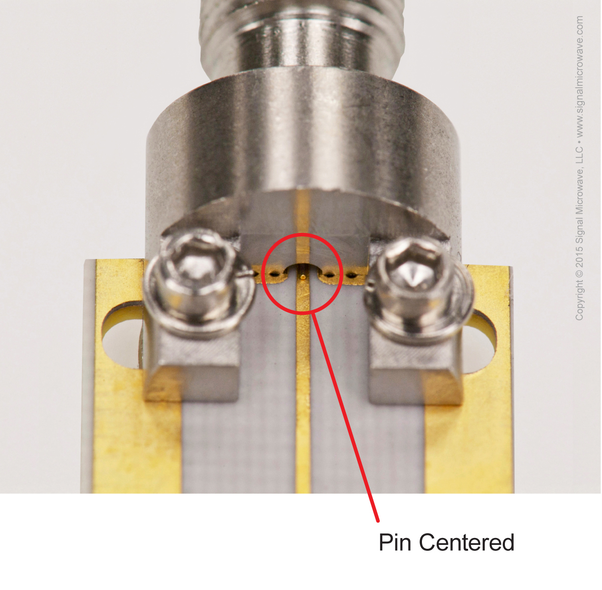
End Launch Pin Alignment Diagram
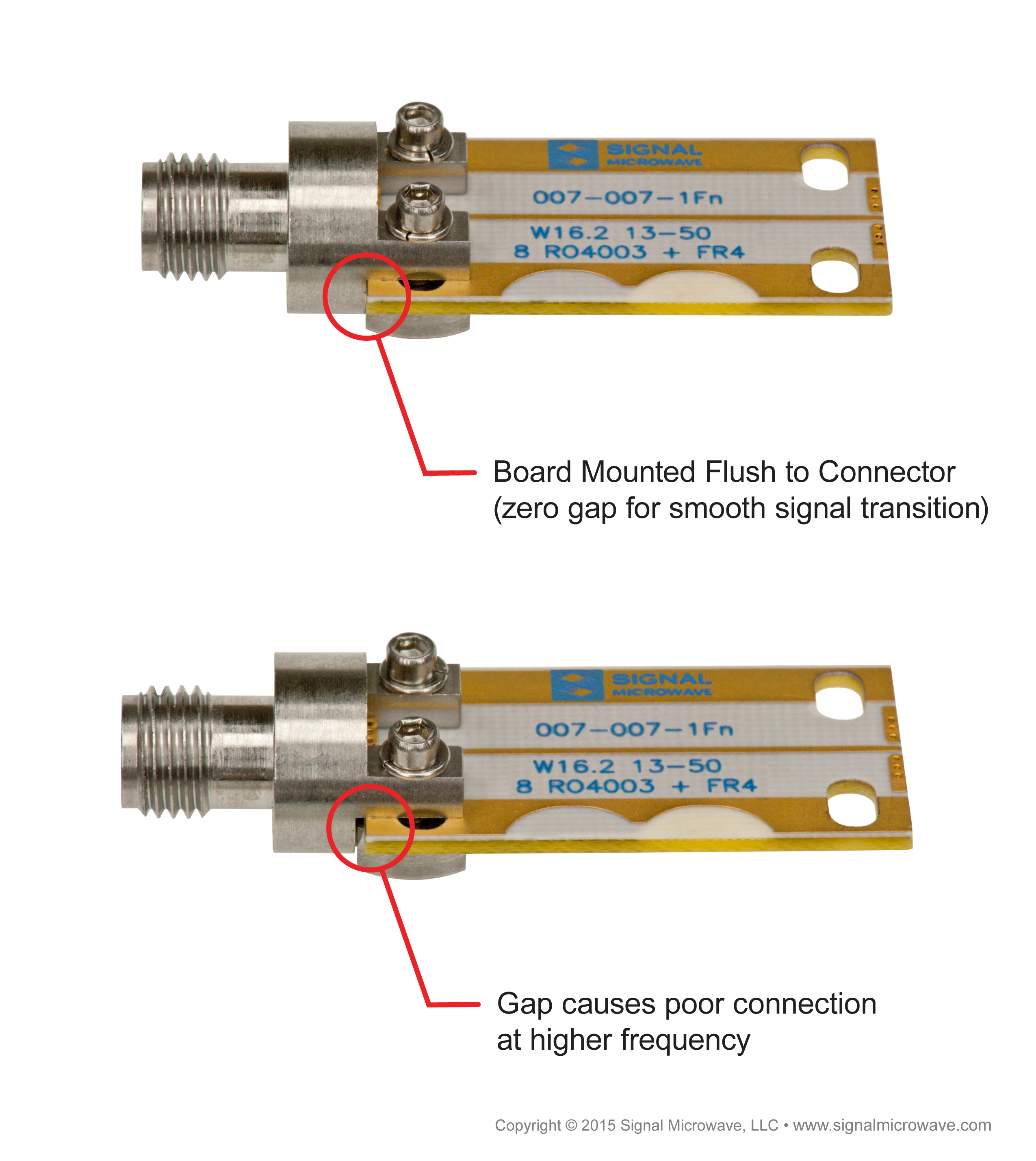
Proper Test Board Alignment
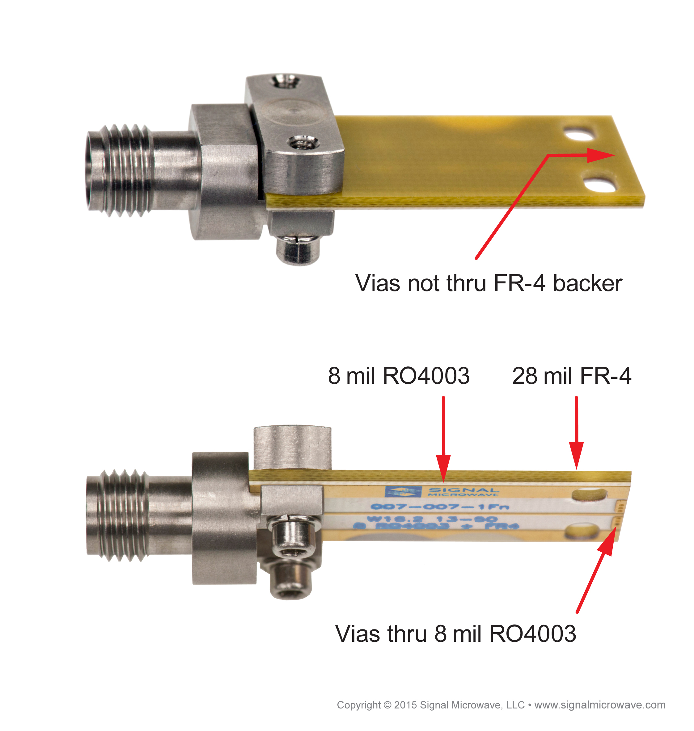
Test Board Details
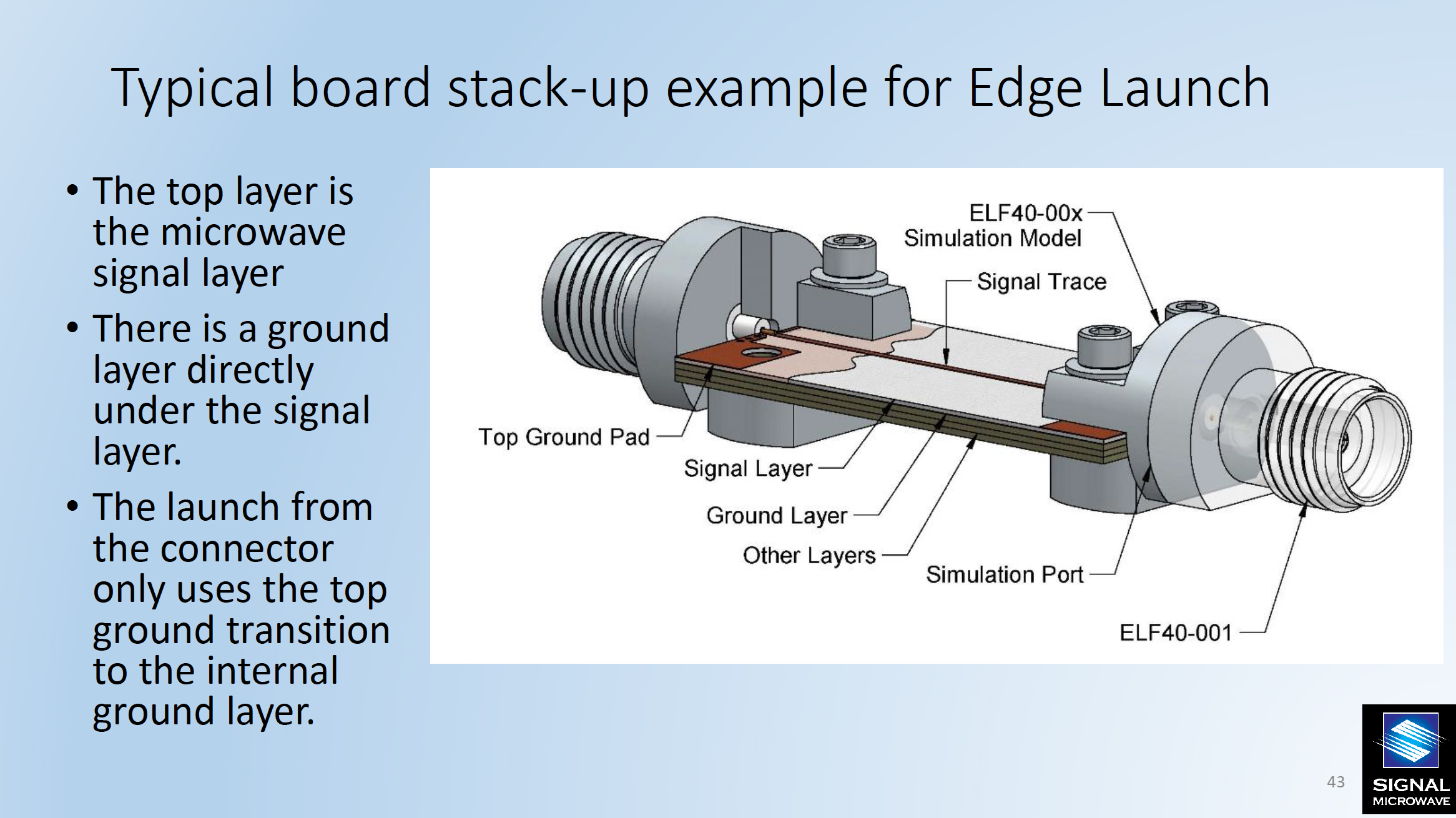
Typical Board Stack-up Example
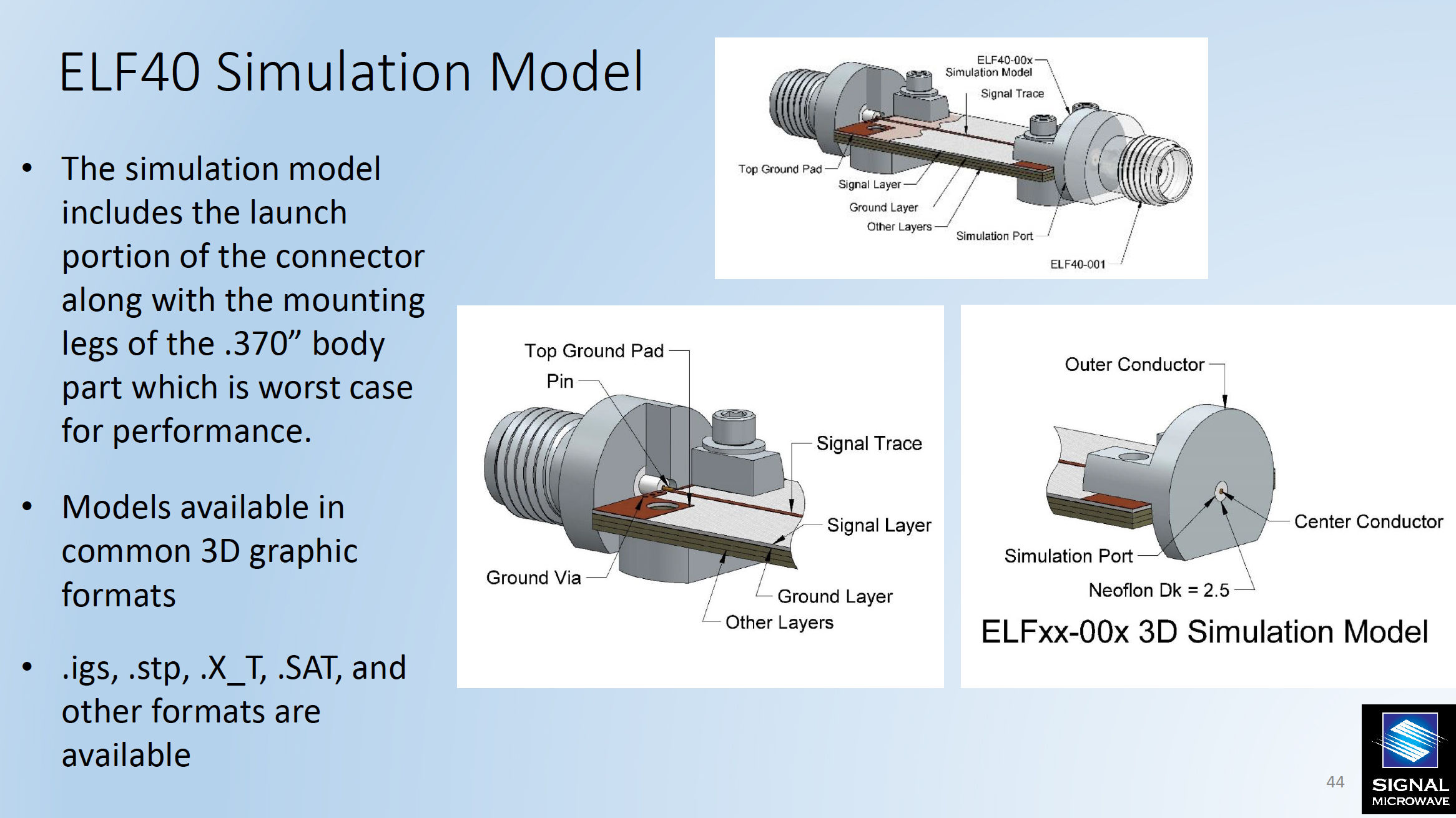
ELF40 Simulation Model
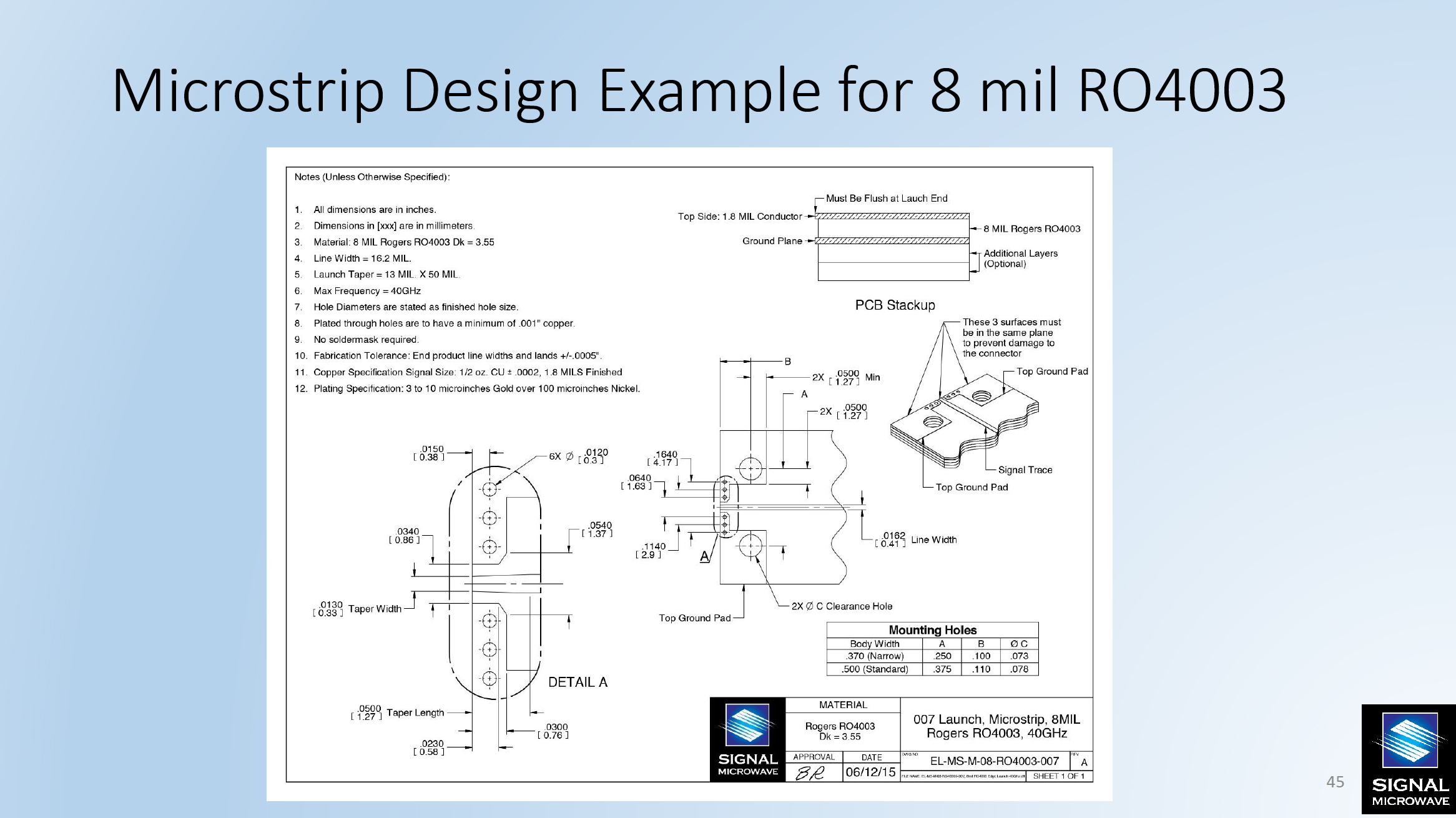
Microstrip Design Example
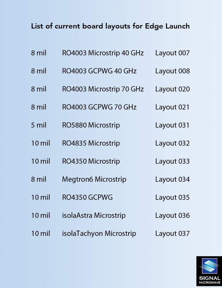
Current Board Layouts (Edge Launch)
Please click the Layout number below to access the technical drawing pdf for each board layout.
| 8 mil | RO4003 Microstrip 40 GHz | |
| 8 mil | RO4003 GCPWG 40 GHz | |
| 8 mil | RO4003 Microstrip 70 GHz | |
| 8 mil | RO4003 GCPWG 70 GHz | |
| 5 mil | RO5880 Microstrip | |
| 10 mil | RO4835 Microstrip | |
| 10 mil | RO4350 Microstrip | |
| 8 mil | Megtron6 Microstrip | |
| 10 mil | RO4350 GCPWG | |
| 10 mil | isolaAstra Microstrip | |
| 10 mil | isolaTachyon Microstrip |
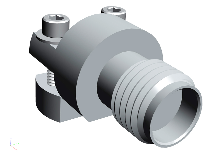
ELF67-001 3D PDF
Please Click the PDF 3D icon to download the file to your computer and open in Acrobat Reader for 3D functionality (won’t work in browser)

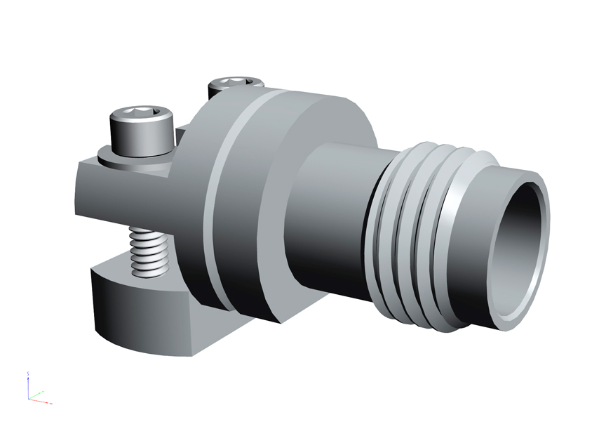
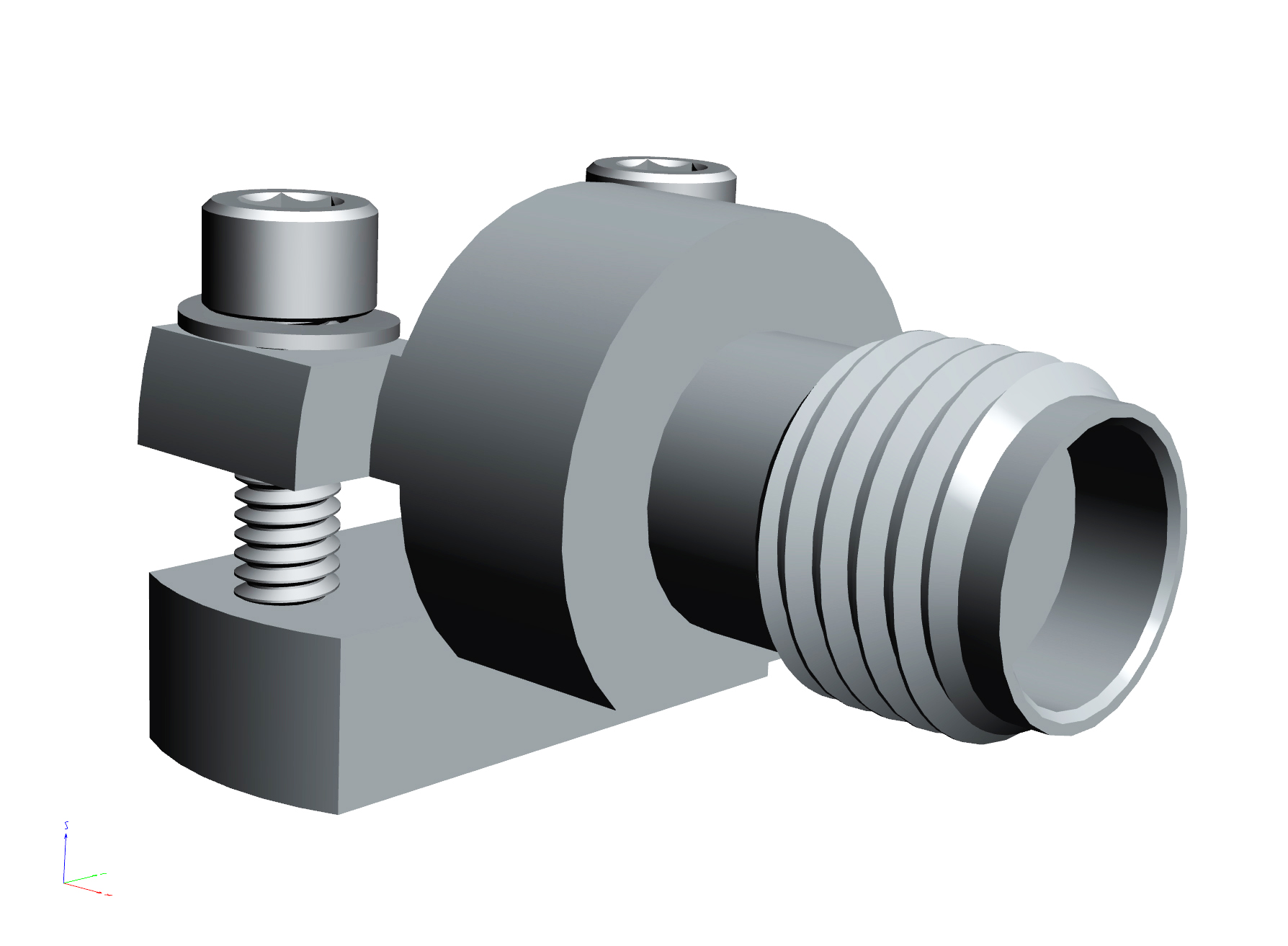
ELF40-001 3D PDF
Please Click the PDF 3D icon to download the file to your computer and open in Acrobat Reader for 3D functionality (won’t work in browser)
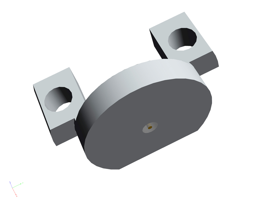
ELF40-002 3D PDF
Please Click the PDF 3D icon to download the file to your computer and open in Acrobat Reader for 3D functionality (won’t work in browser)
ELFxx-00x Simulation Model 3D PDF
Please Click the PDF 3D icon to download the file to your computer and open in Acrobat Reader for 3D functionality (won’t work in browser)


